
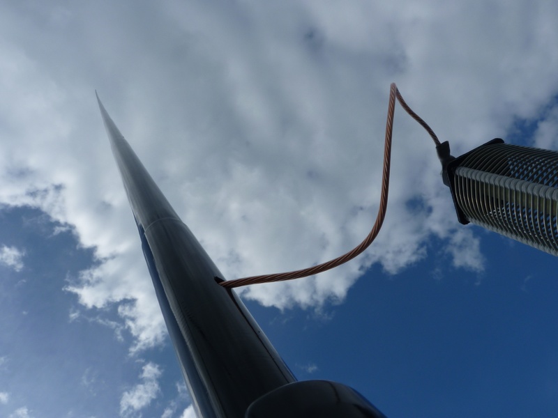
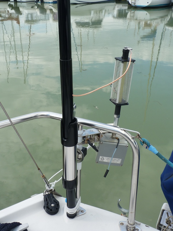
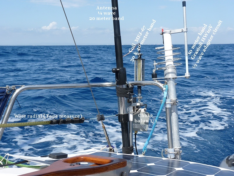
The quarter wave fiberglass antenna for the 20 metre band connected to the MFJ-67 coil for use on 30 or 40 metre band.
The antenna used during the 2018 season was a vertical consisting of telescopic MFJ-1979 5.20 meters long which is a quarter wave on the 20 meter band. It was attached to the aft balcony of the boat using a jaw mount. This antenna and its support are entirely made of stainless steel and are particularly suitable for the marine environment. A high quality 1/1 ratio choke balun is installed at the base of the antenna. This balun, manufactured by “Balun Designs LLC” is enclosed in a waterproof case. On 40 and 30 meters, a coil (MFJ-67) is inserted at the base of the telescopic whip.
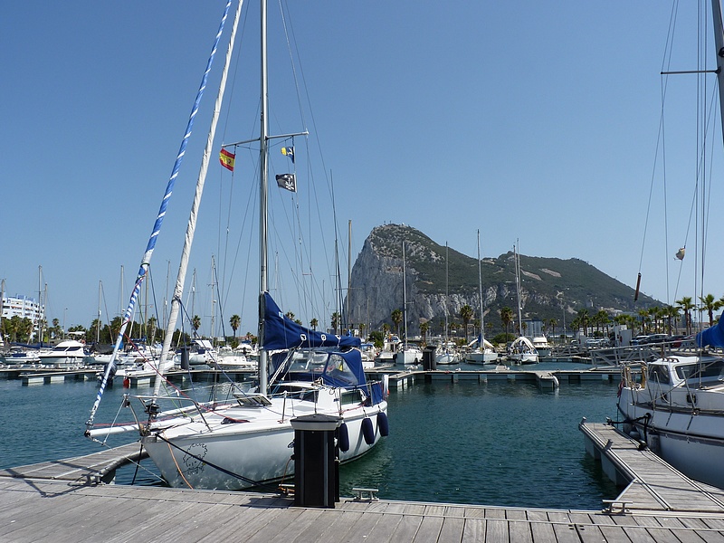
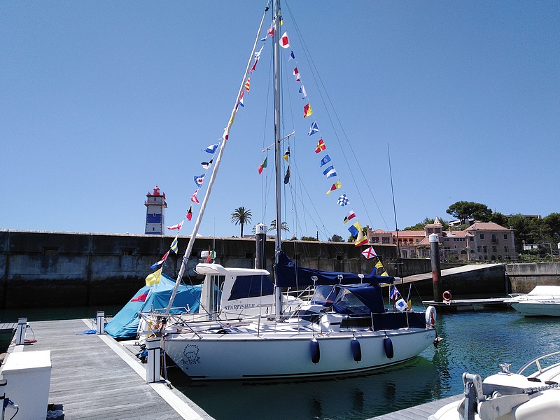
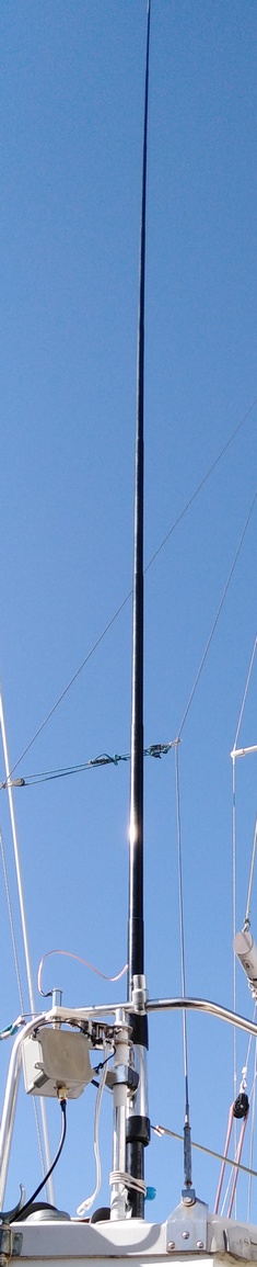
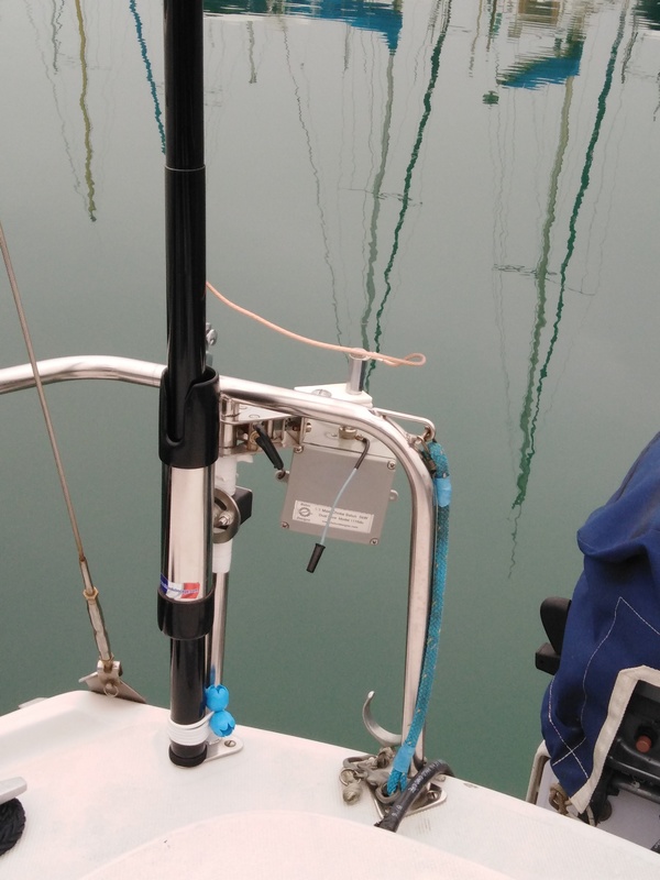
Unfortunately the MFJ-1979 antenna is not able to support strong wind and movements of the boat, so the antenna could not be used at sea. It was replaced by a 6 meter long telescopic fibreglass pole into which a 5.28 meter long special antenna wire was inserted. This way the antenna can withstand very strong winds (tested in 60 knot winds). The image above and the one to the right show the general appearance of the antenna.
This antenna requires the use of a counterpoise and therefore a horizontal radial has been added.
Antenna adjustment
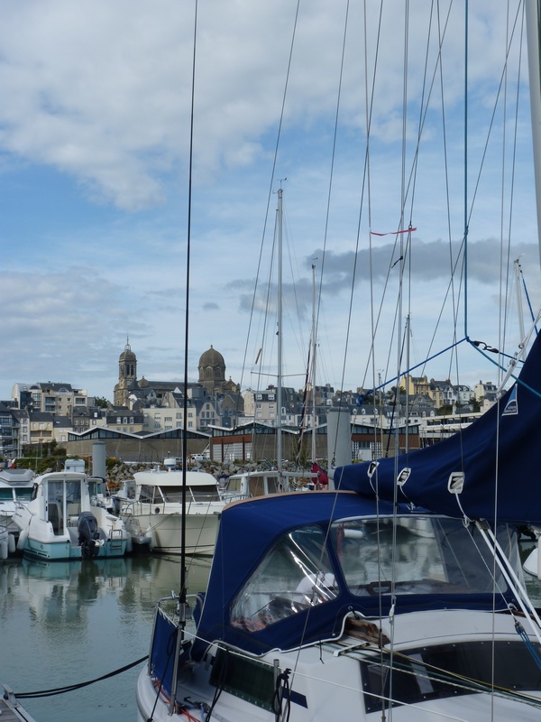
An antenna placed on a sailboat is significantly influenced by the metal standing rigging (mast, shrouds, lifelines, rails, railing, metal strakes, etc.) because of its proximity. The entire rigging exerts a capacitive effect on the antenna. If others boats are in its close vicinity, their rigging will also exert an influence on the antenna. It is therefore essential to adjust the resonance of the antenna when the boat is alone in a secluded place (eg at anchor). Note that when the boat is again surrounded by other rigging (in the marina for example) the antenna will appear out of adjustment. However, if the VSWR of the antenna has been set to 1/1 this disturbance should only be around 1.5/1 and we remain in an acceptable zone if we want to use the radio station when staying in a harbour.
Adjustment of the 20 meter quarter wave antenna
Present-day transceivers now have an integrated VSWR meter. Antenna tuning can be done simply by measuring the VSWR using the VSWR meter or an antenna analyzer. In principle it will not be necessary to change the length of the antenna. It will simply be enough to lengthen or shorten the radial to achieve a low VSWR. It should be noted that this adjustment includes an assembly formed by the antenna, the radial and also the metal standing rigging. On the 20 meter band with a low VSWR centered on 14.150 MHz, the VSWR stays very low over the entire band, however it can slightly rise at the ends.
Below is a picture showing the SWR of the antenna mesured when the boat is in the harbour.
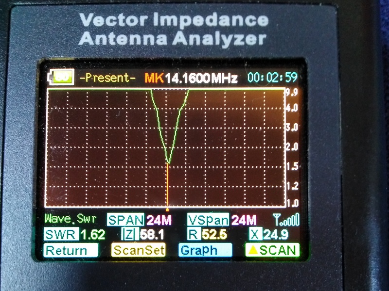
SWR measured in the harbour on 14 MHz
Tuning the 20 meter quarter wave antenna to the 30 and 40 meter bands
After adding the MFJ-67 coil to the antenna base, the adjustment procedure is the same as above. As these bands are narrow the VSWR stays very low across the entire band.
Turning the 20 meter quarter wave antenna to a half wave on the 10 meter band
Here we need to use an impedance adapter circuit. The feed impedance at the very end of a half wave is several thousand ohms, typically between 2,000 ohms and 5,000 ohms, which we must match to our 50 ohm transceiver. The problem with end feeding a half wave antenna is also its advantage. The high impedance means that the feedpoint has a very high voltage but low current, therefore very little ground is required. A very small counterpoise should be adequate and in this case it was necessary to add a 1 meter radial. For convenience, the impedance adapter circuit was taken from a Grazioli HW10V antenna. This circuit includes a large coil and an adjustable capacitor allowing the centering of the VSWR. This circuit was also selected for its robust construction capable of resisting marine corrosion.
Below is a picture showing the adapters circuits for the 30, 40 and 10 meter band.
Antenna system
The adjustment process is identical to that described above. The centering of the VSWR was done on the 20 meter band resonance frequency multiplied by two, i.e. 28.300 MHz, which allows a very low VSWR range over the first part of the 10 meter phone band. This adjustment also allows working in CW in the lower part of the band.
Below is a picture showing the SWR of the antenna on the 10 meter band
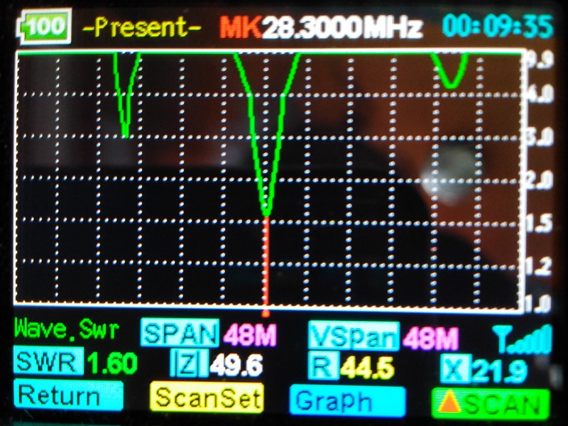
SWR measured in the harbour on 28 MHz
Why not use the backstay as an antenna ?
1 - Inserting the antenna into the backstay does not allow you to choose a resonant frequency because once the antenna is cut and the insulators crimped to the cable, you cannot shorten or lengthen the antenna to adjust it. We cannot determine its length before this process either because it is subject to the influence of the metal standing rigging.
2 - Integrating the antenna into the backstay therefore means using the greatest possible length between two insulators and using a waterproof automatic tuner at the base of the antenna to obtain efficient operation.
3 - We do not resolve the problem of the counterpoise (radial) which remains essential.
In conclusion
On the "Petit Prince 2" sailboat, integrating a quarter-wave antenna into a robust fiberglass rod was the easiest and least expensive way to place an antenna that could work on several HF bands with efficient performance.
Results
The world as well as short distance communication are within range. The clear environment, the very low take-off angle of the wave due to this antenna, the reflection on the salt water and the propagation do the rest.
* * * * * * * * * * * *
{Back to top}
(experimental)
* * * * * * * * * * * *